I-Beam Climbing Robot
-
Objective
The robot must climb continuously up an 41.7 degree angled I-Beam for 1.5m while carrying a payload of at least 1kg. The electric motor and planetary gearbox are provided. Any other custom components must be 3D printed.
-
Outcome
Our robot ultimately ended up lifting a maximum payload of 4.8 kg up the angled I-Beam. An applied voltage of 10V was used correlating to a current draw of 1.2 amps. The overall pull time was 152 seconds leaving 28 seconds to spare.

Key Criteria
-
To lift the largest payload possible, we aimed to maximize the power into the system while minimizing power losses along the way. Thus, we used the maximum voltage that could be safely applied; however, at peak power, the maximum current is exceeded. To decrease the current into the system and comply with the maximum threshold, we shifted our motor operating point by increasing the motor speed. To fully optimize our design, a custom gear stage was required to increase output torque and decrease output speed, allowing us to utilize the entire available lifting time.
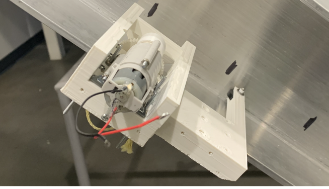
From this, combinations of gear ratios and driven wheel sizes were determined that allowed the robot to complete the task in the fixed amount of time. For the driven wheel, we chose to minimize the radius to increase the driving force and limit rolling resistance, which was a concern due to the easily deformable rubber bands we were using to increase the coefficient of friction. With the minimized wheel radius, our custom gear required a gear ratio of 7.5:1 to achieve the required velocity. To limit power losses, we accomplished this in one stage with an 8 tooth input gear and a 60 tooth output gear.
-
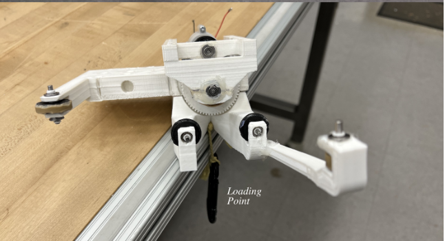
To maximize the normal force on the wheel, we placed the driven wheel in between the bottom idler wheels and the point where the weight would be loaded to create a mechanical advantage. This also decreases the normal force on the idler wheels, limiting energy loss from friction at this contact point. The placement of the load further impacts the amount of normal force on the driven wheel. Placing the weight further from the driven wheel increases the lever arm and thus increases the normal force. However, this also increases stress in the structural elements of the chassis, so an intermediate point had to be used.
-
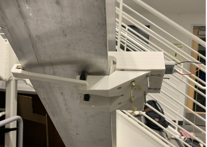
Through testing, we determined that increasing the lever arm of the weight also increases the robot’s propensity to spin, causing problems with steering. Small initial errors in alignment are magnified over the large distance the robot must travel. To allow for incremental corrections of the robot’s path, two rollers were added that make contact with vertical surfaces of the I-beam on opposite sides, accounting for necessary adjustments in both lateral directions. Although these increase potential frictional losses, they were not expected to have large normal forces and were intentionally placed at a distance from the robot’s body in order to further decrease the normal forces experienced.
Transmission
To optimize mechanical power out, electric power into the system must be maximized, which increases with both voltage and current. To prevent overheating, the maximum voltage of 10V was applied and the maximum current given the 180 second time constraint was determined. However, at peak power, maximum current is exceeded. To decrease current, motor speed can be increased. The motor speed that maximizes power while meeting the current limit is 3607 rad/s and shifts our operating point closer to maximum efficiency, shown graphically below.


To maximize the payload by utilizing the full time allowed, a custom gear was required to increase the output torque and minimize the output speed. With a 125 second task duration (high FoS to account for large degree of uncertainty), numerous combinations of wheel radii and gear ratios allow the robot to travel at the required velocity and were determined in Matlab.
Chassis
The most critical part of the robot is where it contacts the I-beam as this determines if it will be in static equilibrium and if enough normal force will be on the driven wheel to prevent slipping. As such, the chassis is largely dictated by filling in material around these points of contact while ensuring the chassis can structurally support the desired load. Low fidelity prototypes allowed us to determine what contact points allowed for static equilibrium on the beam under loading but without the applied torque from the motor.
In our design, the robot sits on the flange of the I-beam. The driven wheel rests on top of the flange with two idler wheels along the bottom surface that are in a line with each other but offset from the driven wheel. These were intentionally offset from the driven wheel to create a mechanical advantage that increases the normal force on the driven wheel while at the same time minimizing the normal force on the idler wheels. Two rollers were added that make contact with opposite vertical faces of the I-beam in order to help with steering and make minute corrections caused by slight misalignments. As such, we did not expect these rollers to experience large normal forces.


As previously mentioned, the normal force on the driven wheel is a critical parameter. If the driving force exceeds the friction force, slipping will occur. In our analysis, we determined two dimensions that contribute most largely to the normal force, the perpendicular distance between the idler wheels and the driven wheel (d) and the distance between the driven wheel and the payload (x). With preliminary calculations and the listed simplifying assumptions to account for static indeterminacy, we determined the relationship below that allows for appropriate chassis dimensions that prevent the robot from slipping.
Driven Wheel
The ultimate goal of our driving wheel is to maximize the driving force. Thus, for a fixed output torque, the wheel radius should be minimized. The smallest radius possible for our design given constraints from the chassis was 10mm. To increase the coefficient of friction and subsequent allowable driving force, rubber bands were adhered to the PLA wheel with super glue. A smaller wheel radius also decreases the rolling resistance that must be overcome, which we expected to be significant due to the easily deformable surface of the rubber bands. It is important to note that having a small wheel radius introduces other problems, so trade offs must be considered. Smaller wheel radii will lose more energy from collisions and also from shaft friction. However, the aluminum I-beam appears to have a relatively smooth surface and the ball bearings have a low coefficient of friction, so these energy losses were expected to be small. Thus, we prioritized radius minimization, while ensuring it could still overcome impact from collisions without huge energy losses.


When introducing the interaction of the chassis and wheels, we determined that the driven wheel should be simply supported, rather than cantilevered. This allows the forces in the ball bearings to be minimized (roughly halved) while still supporting the large normal force on the driven wheel that is necessary to prevent slipping. FEA confirms that the wheel can withstand expected loading. A bearing support was applied to the wheel inner radius, a face on the tooth of a gear was fixed to simulate stall (a conservative estimate), and the expected torque of 6.9Nm was applied to the wheel contact point on the I-Beam.
Custom Gear
The transmission analysis tells us that given our chosen wheel radius of 10mm, a gear ratio of 3000 is required to maximize power. With the 400:1 gearbox set, this means an additional custom gear of 7.5 must be added. To limit losses in efficiency, we chose to accomplish this gear ratio in one stage. To limit force multipliers and ensure proper alignment, we wanted both gears to be simply supported rather than cantilevered. This placed a constraint on the smaller input gear as a shaft had to fit through its center. With a limit on the diameter, the smallest gear we felt comfortable using had eight teeth. Thus, an output gear with 60 teeth was required.


The coefficient of friction is very low for a shaft running on bearings (μ=0.002), so losses here are small. Thus, the sliding friction dominates the custom gear efficiency, and the overall efficiency of the custom gear was found to be 0.96. This relatively high efficiency tells us that while there will be added power losses with the introduction of a custom gear, this will be greatly offset by the increased torque it provides.
To confirm our custom gear would be able to accommodate the expected output torque of 6.9 Nm, FEA was run on an assembly with both gears. The expected torque was applied to the input gear. A bearing support was placed on the input gear shaft and a fixed constraint was placed on the output gear shaft. This simulates the gears at stall which is a conservative estimate of the stress that will be experienced. As expected, the small gear experiences the highest stress concentrations and was the limiting factor in testing.